The most powerful feature of the Signetics 2636 Programmable Video Interface (PVI) are its four reprogrammable objects. Several sources cite this Signetics chip (c.1977) as being the first commercially available hardware implementation of a memory mapped object on a video chip. This type of graphical object has since come to be referred to as a sprite, but I prefer to use the terminology Signetics used in their data sheet.
The shape of each object is defined by a block of ten bytes, creating 80 pixels organized as 10 lines of 8 bits. The pixels within one object are all the same colour. The colour of each object is set by three bits, giving a choice of eight colours.
The size of each object can be set independently to one of four different sizes. Each object can have a height of either 10, 20, 40 or 80 lines, and the widths are scaled similarly to 8, 16, 32 or 64 horizontal clocks.
The position of any object on the screen is set by its corresponding horizontal and vertical coordinates with the origin at the top left of the screen. The coordinates can be any eight bit value, but a horizontal coordinate greater than 227 pushes the object off the right hand side of the screen, and vertical coordinate greater than 252 will be off the bottom of the screen.
This is straightforward so far. The power of these objects comes from the fact that they can be output again further down the screen. And again and again…. In fact it is possible to have up to 80 objects on the screen at one time. These are referred to as duplicates. A duplicated object will always be below its predecessor, and they cannot overlap. The horizontal coordinate of a duplicate is simply the distance from the left edge of the screen, in the same way that the original duplicate is specified. The vertical position of a duplicate is trickier; it is set as a vertical offset from its predecessor.
It is also possible to reprogram the shape, size and colour of an object between duplicates, but that requires some real-time programming, and we will get to that in a later tutorial. For now, lets look at a simple example in a static screen.

The PVI has four such objects, each defined by 14 registers called an object descriptor, comprised, in order, as 10 bytes of shape data, a horizontal coordinate(HC), a horizontal coordinate for the duplicates(HCB), a vertical coordinate(VC) and a vertical offset for the duplicates(VCB). These are the coordinates of the objects on the screen above:
| object 1 | object 2 | object 3 | object 4 | |
| HC | 10 | 40 | 60 | 100 |
| HCB | 10 | 35 | 120 | 110 |
| VC | 20 | 60 | 90 | 0 |
| VCB | 20 | 10 | 250 | 255 |
Object 1 has a horizontal coordinate of 10, as do its duplicates. Its vertical coordinate is 20, and all of its duplicates are offset vertically by 20 from its predecessor.
Object 2’s duplicates are shifted 5 pixels left, and offset vertically by 10.
Object 3 is all on its own. Its duplicate has been pushed off the bottom of the screen by setting the vertical offset to 250.
Object 4’s duplicates are all touching. This is achieved by setting the offset to 255. This may seem a little odd, but if 255 is converted to 8 bit binary and then interpreted as a signed two’s complement number, we get -1. This is because VCB has to be set to “the number of lines -1” that you want to be skipped. If you want a gap of just one line, set VCB to 0 and so on.
Each object descriptor therefore consist of 14 bytes of data:
| 0-9 | Shape definition |
| A | HC – horizontal coordinate of primary object |
| B | HCB – horizontal coordinate of duplicate object |
| C | VC – vertical coordinate of primary object |
| D | VCB – vertical coordinate of duplicate object |
The four object descriptors are located at these addresses within the console’s memory map:
| Object descriptor 1 | 1F00 – 1F0D |
| Object descriptor 2 | 1F10 – 1F1D |
| Object descriptor 3 | 1F20 – 1F2D |
| Object descriptor 4 | 1F40 – 1F4D |
Lets have a look at the code that programs these object descriptors. You can download the whole program for tutorial 2 at github.com/sig2650/Tutorial-code . First, here is the code that copies the shapes from program memory into the PVI.

This is taken from the .LST list file generated by the assembler. The first column shows the memory address where the line of code is stored. The second column shows the bytes of data output to the .BIN binary file and which the microprocessor executes. The rest is the original .ASM assembler file that I wrote and the assembler read to generate the binary and the list files.
The first line loads register r3 with the value $0E. This is hexadecimal for 14, the number of bytes in each object descriptor. Here I am using Motorola notation where a $ sign indicates that a hexadecimal value follows. The original Signetics format was H’0E’, but I find that annoying to type and the assembler I’m using accepts either style. It may also be because after Voltmace I went on to work on a project using Motorola 6809’s.
The next line fetches our first byte of data that is stored elsewhere in the code at a location labelled ‘one’. Can you find this in the full program code? This is a pre-decremented index instruction that we looked at in Tutorial 1. First, r3 gets decremented, and then the byte of data located at ‘one’ + $0D is loaded into r0.
One important point that you need to know and remember is that indexed operations only work with r0. There is no such instruction as loda,r2 one,r3-. A huge trap for the beginner is that the assembler in Winarcadia doesn’t recognize this error on your part, and codes it up as loda,r0 one,r3- without so much as a warning.
The next line stra,r0 shape1,r3 now saves the value from r0 into the PVI, at address shape1+r3, which is calculated to be $1F0D, the vertical coordinate of duplicate object 1.
The next six instructions perform similar operations for the other three objects.
Finally we get to brnr,r3 loopISe. We discussed this type of instruction in Tutorial 1 so it should be no surprise that it tests r3 and if it isn’t zero it branches back to the label loopISe. So this block of code is executed 14 times and then exits. We now have all four object descriptors loaded with the data for their shape and position. The final thing to look at will be their colour and size.
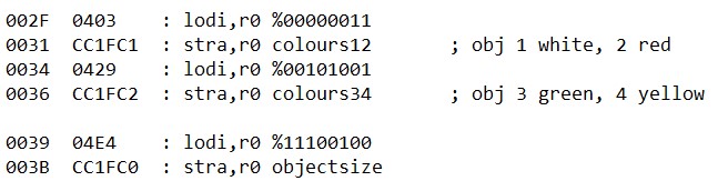
The colour of the four objects are set by two bytes in the PVI at $1FC1 and $1FC2 which I have assigned the labels colours12 and colours34 respectively. The colour of each object is defined by three bits which give the following colour options:
| ~R | ~G | ~B | |
| white | 0 | 0 | 0 |
| yellow | 0 | 0 | 1 |
| purple | 0 | 1 | 0 |
| red | 0 | 1 | 1 |
| cyan | 1 | 0 | 0 |
| green | 1 | 0 | 1 |
| blue | 1 | 1 | 0 |
| black | 1 | 1 | 1 |
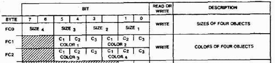
The chart above from the PVI data sheet shows the assignment of the bits in the object colour registers. C1 is red, C2 is green and C3 is blue. Note that these values are active-low, which means we need to set the bit to 0 to turn that colour on. So the value $011 will give a pure red colour while %000 turns all three primaries on to give white.
You should now be able to interpret the binary values written in the example code above and confirm that they correlate with the comments and what you see on the screen. If you have WinArcadia running you could try modifying the program to select other colours and test your understanding.
Finally, the size of each object is determined by two bits in the register at $1FC1, giving the option of four sizes as shown here:
| bit 1 | bit 0 | width in clocks | height in lines |
| 0 | 0 | 8 | 10 |
| 0 | 1 | 16 | 20 |
| 1 | 0 | 32 | 40 |
| 1 | 1 | 64 | 80 |
You should now be able to relate the snippet of code above to the size of the four objects on the screen, and again you can change the values in WinArcadia to verify your understanding. While you are at it, you could also look at the tables of data at labels one, two, three and four and play with the shape and position of the objects.
In the next tutorial I plan to look at the screen colour and the background. The latter is good for creating mazes.
